RF Controllers
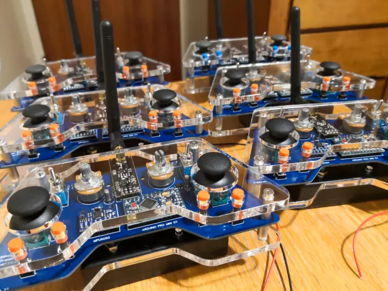
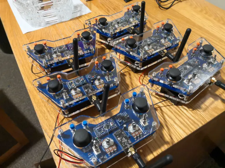
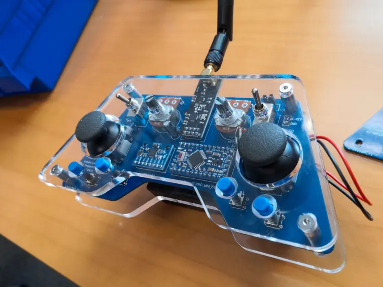
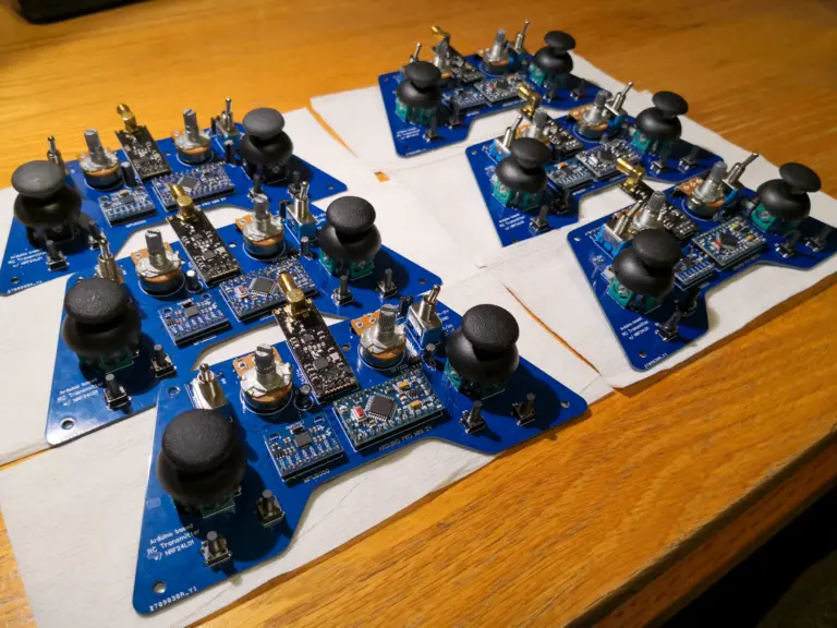
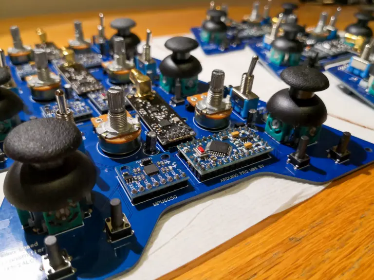
RF controllers and sensor shields assembled for student-built robot cars.
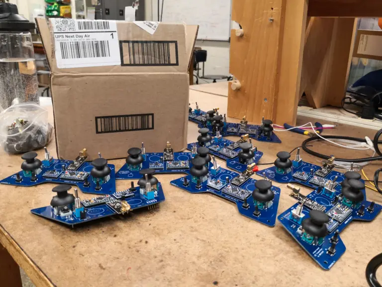
I assembled 25 controllers for the NEET Autonomous Machines sophomore project class, 2.S007 Design and Manufacturing I (of Robotic Systems)!
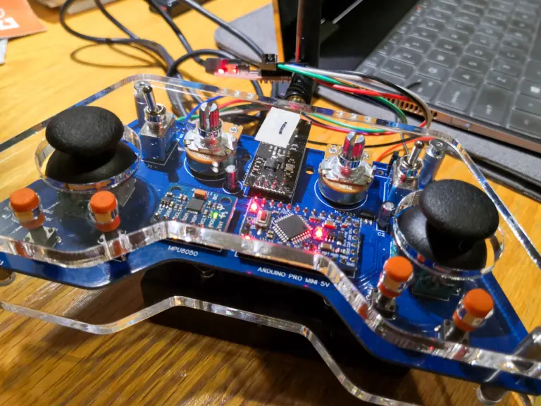
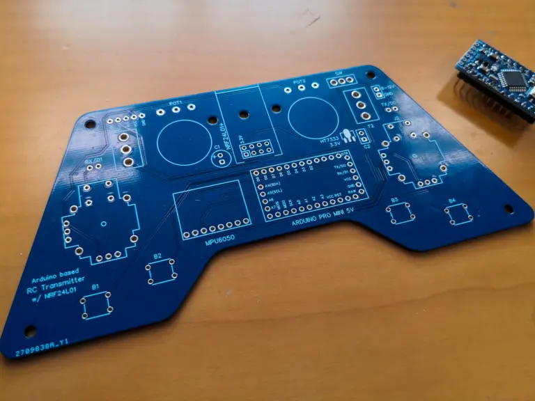
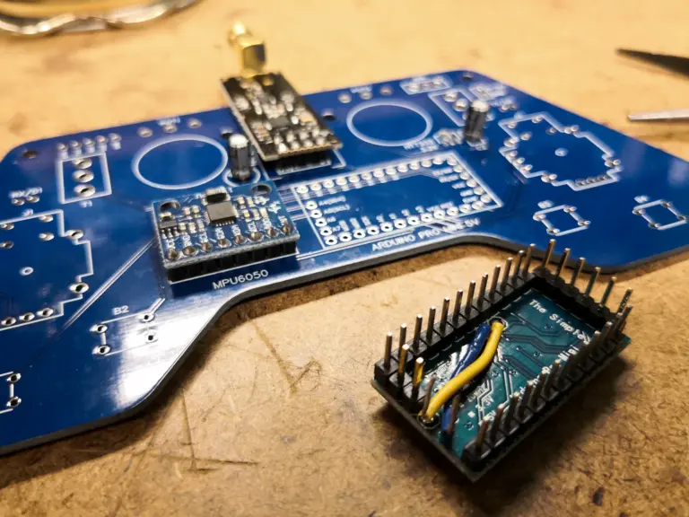
The design was based on a tutorial by How to Mechatronics. Each controller has the following electronics on board: an Arduino Pro Mini, two joysticks, two SPDT toggle switches, two potentiometers, six push buttons, an MPU6050 IMU, and an NRF24L01 transmitter. They also have capacitors, jumpers, and an SMD voltage regulator.
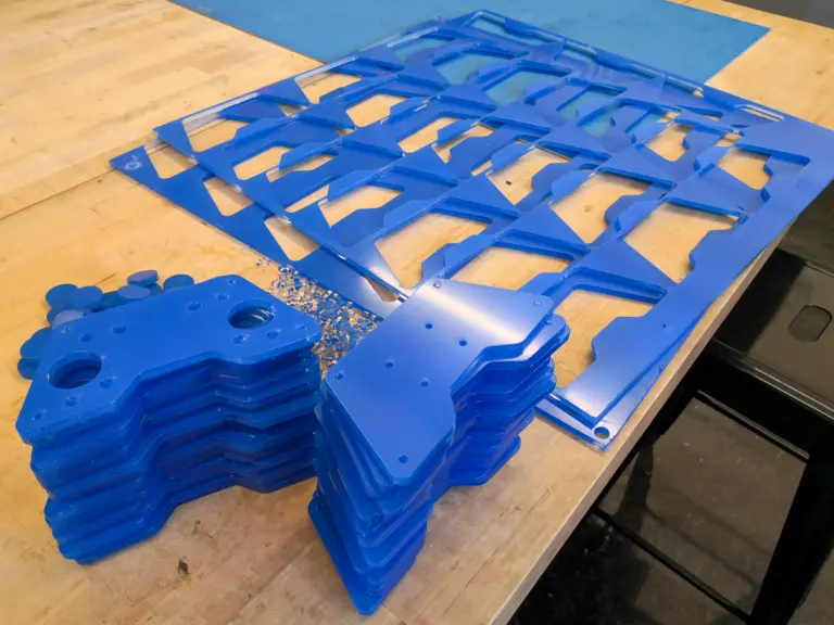
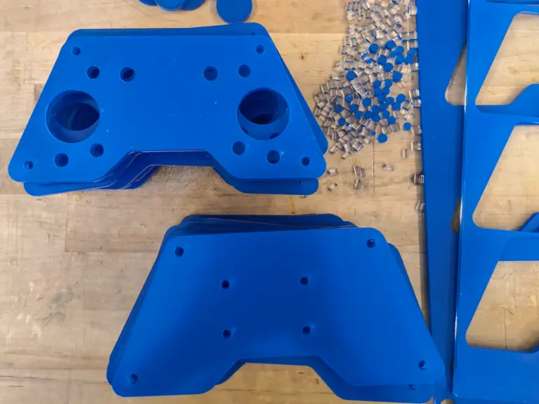
These were all powered by two rechargeable 3.7V Li-ion batteries on the back and enclosed by two laser cut acrylic sheets.
Provided materials
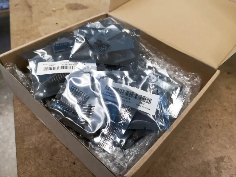
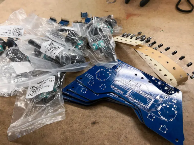
The build used custom PCBs, IMUs, joysticks, capacitors, and a finished controller as a reference.
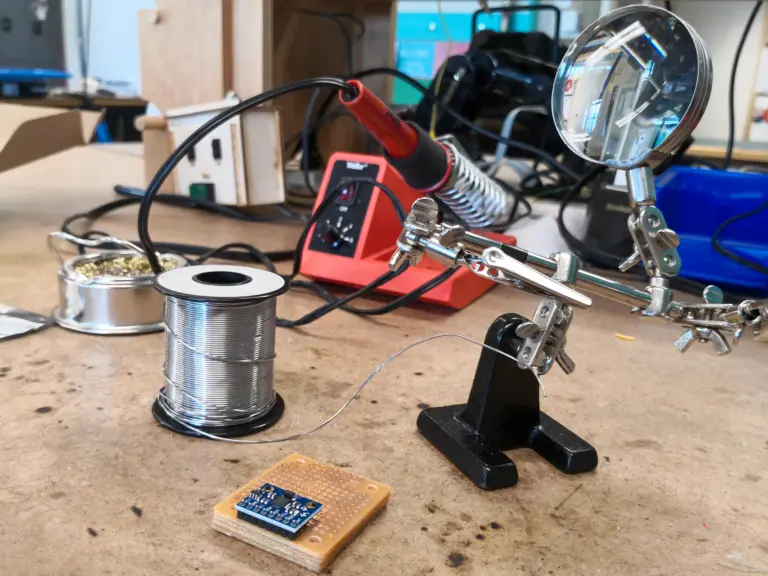
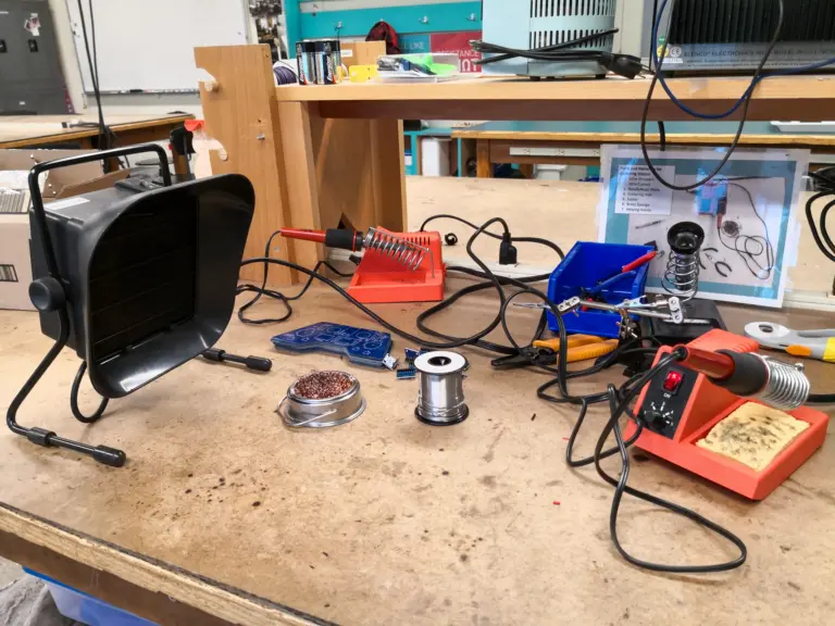
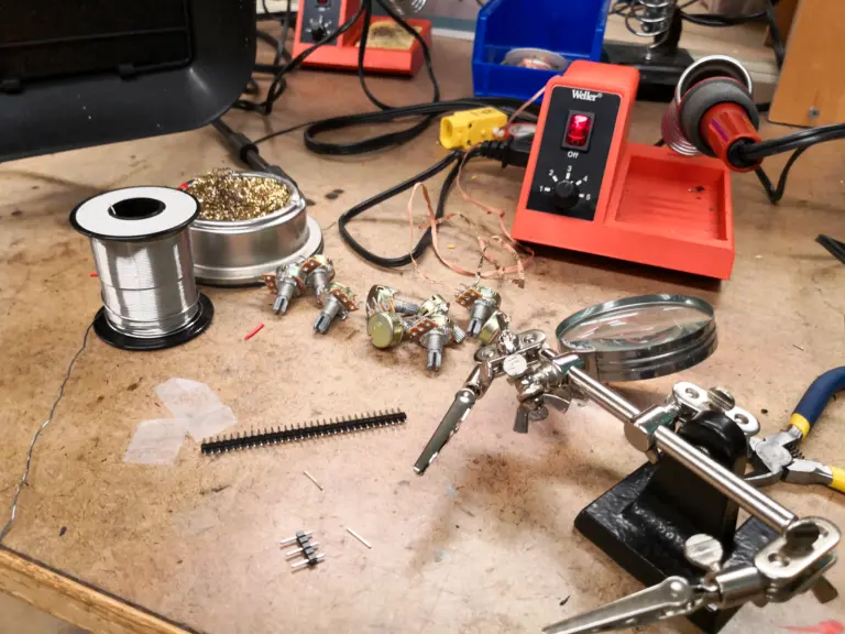
Work station at 4-409
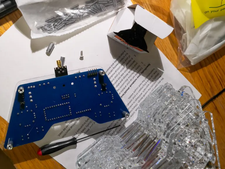
I prepared the work station and soldered the IMUs and headers.
Soldering components
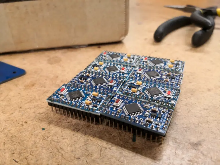
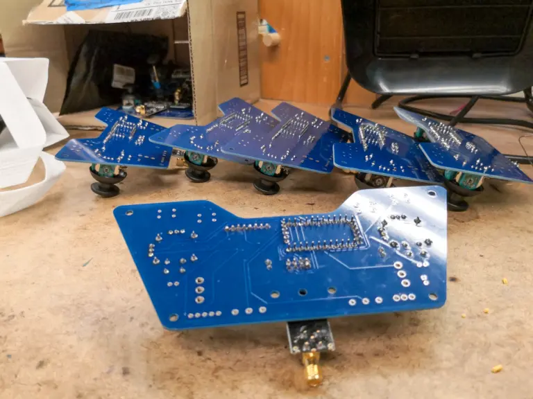
I soldered the Arduino Pro Minis and other components onto the first set of boards. A board-version mismatch required additional wiring before cleaning and testing.
Final assembly
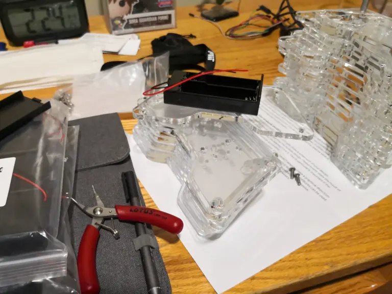
I laser-cut the acrylic covers, assembled the controllers, then tested and debugged them.